
Circuit Board Assembly--An Introduction
Circuit Board Assembly—An Introduction
Within electronic equipment, one can find one or several printed circuit boards (PCBs). Each of these PCBs may have many passive and active electronic components mounted on them. Circuit board assembly, PCB Assembly or PCBA are industrial names for such a combination of a PCB and several electronic components on it. However, the circuit board assembly may also contain other non-electronic components, parts, or accessories like heat sinks, shields, connectors, and wires. Advancing technology and user demands are forcing manufacturers to make compact electronic equipment—making PCB Assembly an important issue.
To make thinner and smaller electronic equipment, component manufacturers are reducing the size of components and increasing the complexity of integrated circuits they manufacture. To facilitate mounting such tiny components, PCB manufacturers are increasing the density of their boards by adopting advanced technologies like HDI. As it becomes increasingly difficult to manually handle and mount small components, engineers are making special machines for handling them. All these activities are resulting in many types of circuit board assemblies depending on their design and application:
- Assembly with Through-Hole Components
- Assembly with Surface Mount Components
- Assembly with Mixed Components
- Assembly on Single Side of Boards
- Assembly on Both Sides of Boards
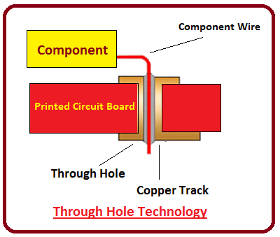
Assembly with Through-Hole Components
The industrial name for components with long wire leads is Through Hole Components or THC. Boards assembled with THCs must have holes in them to accommodate their leads. In manual assembly, the operator pushes the THC leads through the holes until the component body is flush with the board. The assembly then proceeds to the wave soldering process, and thence to a lead-cutting machine.
In high-speed automated assembly, a programmable machine prepares a tape of the THCs for automatic insertion. An insertion machine then pre-cuts the leads of the components, inserts them into the board, and clinches the leads before the assembly enters wave soldering.
Assembly with Surface Mount Components
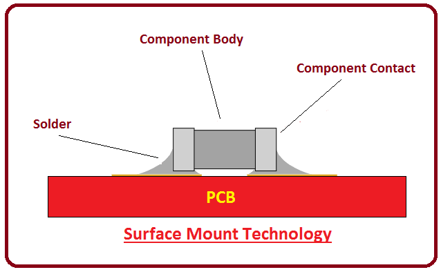
With advancing circuit complexity, the designer must increase the number of components on the PCB. Manufacturers are making smaller components in surface mount packages to facilitate this component density. Components made with surface mount component (SMC) technology offer several advantages over THC. SMCs are substantially smaller than THCs, and unlike THCs, they do not require holes drilled into the boards, reducing the board price to that extent. This allows designers to pack SMCs on board at very high component densities.
Although the component density of a board increases dramatically with the use of SMCs, assembling it requires many new technologies additionally. Rather than using manual operations, machines are necessary for handling the miniature components, mounting them on the board, and soldering them.
Assembly with Mixed Components
Sometimes devices must use components available only in TH packaging. Examples are high-power RF and Microwave devices. These mixed assembly boards use both SMCs and THCs.
Assembly on Single Side of Boards
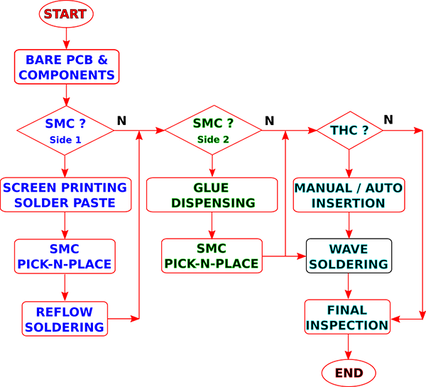
This type of assembly has components only on one side of the board. The board itself may be of a single-layer, double-layer, or multi-layer type. The components may all be only THC, only SMC, or mixed. For mixed assembly, depending on the component density, the process may decide to mount the SMCs first and reflow the board, then mount the THCs and wave solder the circuit board assembly.
For only THCs, the process starts with insertion and proceeds to the wave soldering machine. For only SMCs, the process starts with solder paste deposition on the board, followed by SMC placement, and reflow soldering.
Assembly on Both Sides of Boards
Unlike assembly on a single side of a board, it is also possible to place components on both its sides. Assembly processes prefer to mount all SMCs on the underside and all THCs on the top side before wave soldering the board. It is also possible to mount SMCs on both sides of the PCB. Mounting THCs on both sides of a board leads to severe assembly problems and is not a preferred process.
PCB Assembly Process Technology
Newer assembly processes involve several automated technologies that improve throughput and efficiency over the manual methods. These are:
- Auto-Insertion
- Wave Soldering
- Glue-Dosing
- Solder-Paste Deposition
- Pick-n-Place
- Reflow Soldering
Auto-Insertion : This technology primarily involves mounting THCs on PCBs. The process starts with the preparation of a program for the auto-inserter machine. Based on the inputs, the auto-inserter arranges THCs in a reel. The inputs necessary are the component sequence, their position, orientation, and span.
While mounting components, the auto-inserter machine uses the component reel and sequentially plugs each THC in its respective position. The machine also cuts off the excess leads before insertion, and clinches the leads after insertion to prevent the component from falling off the board. Once the machine completes the insertion process, the board goes for wave soldering.
Wave Soldering : This technology is also suitable primarily for THCs, but it can also solder SMCs mounted on the underside of the board. The machine has a temperature-controlled bath of molten solder. Powerful pumps within the bath push the molten solder through a long slot to form a vertical wave. The operator can control the height of the wave.
A conveyor system carries the circuit board assembly slowly over the solder bath and the solder wave. As the PCB enters the machine, pre-heaters heat up the PCB assembly, and its bottom grazes the top of the solder wave. The solder anchors the component leads to the copper pads on the underside of the PCB. The conveyor then takes the soldered PCB assembly to a cooling zone to bring its temperature down.
Some wave soldering machines use a selective soldering technique. These machines use a solder nozzle to generate a small vertical spot wave rather than a long vertical wave. Although it is easier to control the temperature of the spot wave more closely than for a long wave, the machine must move the spot wave physically across the width of the PCB to solder all joints as the conveyor moves the board forward.
For proper soldering, it is important to control various parameters of the wave soldering machine. Of these, most important are the speed of the conveyor, temperature of the molten solder, height of the solder wave, transverse speed of the spot wave, and the pre-heat temperature of the board. A trial run is necessary to establish these parameters. Once the operator reaches a suitable combination, they store it as a profile for the specific circuit board assembly.
Glue-Dosing : This technology is for boards that have SMCs on their underside and THCs on the top. Glue-dosing prevents SMCs from falling off the board while inserting THCs and when it enters the wave soldering machine for soldering the THCs.
A glue-dosing machine deposits a small drop of glue on the underside of the board at the position of each SMC. Once the placement machine has finished placing all the SMCs, the board must undergo a curing process to dry and fix the glue, and anchor the SMCs. After the operator has finished inserting the THCs, the circuit board assembly can proceed for wave soldering.
Solder-Paste Deposition : Meant only for SMCs, this technology facilitates easy soldering for these tiny components as they do not have leads and therefore, do not require holes for mounting them.
The operator uses a stencil for solder paste deposition. This is a thin metal plate with openings in it corresponding to pads on the PCB. The operator must place the stencil on the PCB, registering it accurately. Using a rubber or metal squeegee, the operator forces the solder paste through the openings of the stencil, depositing it on the pads of the PCB. The amount of solder paste deposit depends on the thickness of the stencil.
Pick-n-Place : Another technology exclusive to SMC, these machines handle the tiny components, picking them up from their tape or reel packaging and placing them at specific positions on the PCB. SMC manufacturers offer these components arranged in trays, tubes, reels, or cassettes. The operator programs the machine to pick the right component from its package and place it at its respective location on the solder paste or glue on the PCB.
Reflow Soldering : This is the last stage in the assembly process before the circuit board goes for testing. This technology solders SMCs to the PCB. The machine has a long chamber through which the circuit board assembly travels on a conveyor. Infrared heaters placed in different regions or zones of the chamber maintain them at different temperatures beginning with pre-heat, soak, and reflow, before ending with a cooling zone. The temperature gradually rises from the preheat zone through the soak zone, and maximizes at the reflow zone, where the solder paste melts. Thereafter, the board enters the cooling zone, where the temperature drops off, allowing the solder to solidify and anchor the component to the board.

